As-Built Drawing Accuracy: Tolerances & LOA Standards
As-built drawing accuracy defines how closely as-built documentation matches the real building conditions measured on site. For architects, engineers, and contractors, accuracy should be discussed through measurement tolerances, Level of Accuracy standards,…
Quick Answer
As-built drawing accuracy defines how closely as-built documentation matches the real building conditions measured on site. For architects, engineers, and contractors, accuracy should be discussed through measurement tolerances, Level of Accuracy standards, scan method, deliverable scope, and quality control. Accurate floor plans for renovation reduce design assumptions, support contractor coordination, and help prevent change orders caused by incorrect existing-condition information.
Executive Summary
As-built drawing accuracy matters because renovation, retrofit, construction coordination, and permit-related workflows depend on reliable existing-condition information. A drawing can look professional but still be wrong if it is based on outdated plans, rough field notes, incomplete site access, or unclear tolerances. Architects, engineers, and contractors should not ask only for “as-built drawings”; they should ask what accuracy is required, how it will be measured, what tolerance applies, which deliverables are included, and how the final files will be checked. Level of Accuracy standards, including USIBD LOA specifications, help project teams define how closely the documentation should represent real-world conditions. Manual measurement may be enough for simple low-risk spaces, while 3D laser scanning can provide a stronger measured base for complex buildings, tight coordination, CAD drafting, Revit modelling, and scan-to-BIM workflows. The practical takeaway is simple: accuracy should be specified before measurement begins, verified before delivery, and matched to the project risk.
As-Built Drawing Accuracy: Tolerances, LOA Standards, and Why They Matter
What As-Built Drawing Accuracy Means
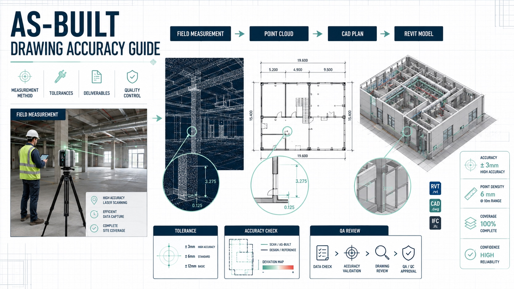
As-built drawing accuracy is the degree to which drawings, CAD files, models, or floor plans represent the actual building as measured on site. It applies to wall locations, openings, levels, stairs, columns, visible structural elements, ceilings, exterior conditions, and other documented features within the agreed scope. For architects, engineers, and contractors, accuracy is not only about neat drafting. It is about whether the documentation can be trusted for design, coordination, pricing, and construction decisions.
As-built drawing accuracy depends on several factors. The measurement method matters. The building complexity matters. Site access matters. The deliverable format matters. A basic PDF floor plan, a renovation-grade CAD package, and a scan-to-BIM model do not need the same tolerance or level of detail. A project team should define accuracy expectations before the site visit so the measurement provider captures the right information from the start.
Accurate floor plans for renovation are especially important because renovation work starts from existing conditions, not from ideal design geometry. Older buildings may have walls that are not straight, floors that are not level, undocumented changes, tenant improvements, hidden constraints, or previous construction that does not match old drawings. If the as-built base is wrong, the proposed design may inherit the same errors. The practical rule is to verify existing conditions before building design decisions on top of them.
Why Accuracy Matters for Architects, Engineers, and Contractors
Architects need accurate as-built drawings because design decisions often depend on existing dimensions, openings, levels, ceiling heights, exterior relationships, and structural constraints. If the floor plan is wrong, the proposed layout may conflict with the real building. This can lead to redesign, additional site visits, consultant questions, or permit drawing revisions. Accurate documentation helps architects start from a more reliable base.
Engineers need accurate as-built information because structural, mechanical, electrical, and plumbing decisions often depend on real-world clearances and existing conditions. A beam location, slab edge, ceiling height, column position, shaft, or visible service route can change the feasibility of proposed work. Engineering assumptions based on outdated drawings can create coordination problems later. Better existing-condition documentation helps reduce those assumptions.
Contractors need accurate drawings because estimates, sequencing, material quantities, demolition scope, and installation planning depend on the drawings they receive. If the documentation is incomplete or inaccurate, contractors may add contingencies, exclude uncertain work, or issue change orders when field conditions differ. Accurate as-built drawings do not eliminate every construction unknown, but they can reduce avoidable measurement-related surprises.
What LOA Means in Building Documentation
LOA stands for Level of Accuracy. In building documentation, LOA helps define how closely a drawing, model, or documented element should match the measured real-world condition. Instead of saying “make it accurate,” the project team can define what accuracy is required and where it matters most. This creates clearer expectations between the owner, architect, engineer, contractor, and measurement provider.
The USIBD LOA specification is commonly used in the building documentation industry to help standardize accuracy expectations. The main idea is simple: different project elements may need different accuracy levels. A wall used for early planning may not need the same tolerance as a steel connection, a prefabricated component, a tight MEP coordination zone, or a critical clearance. LOA helps avoid vague language and makes accuracy easier to discuss.
LOA should not be treated as a marketing label. A provider should be able to explain how they will achieve the required accuracy, what measurement method they will use, how the deliverable will be verified, and what areas or elements are outside scope. The practical takeaway is that LOA is useful only when it is tied to project purpose, deliverables, tolerances, and quality control.
LOA and USIBD Standards in Plain Language
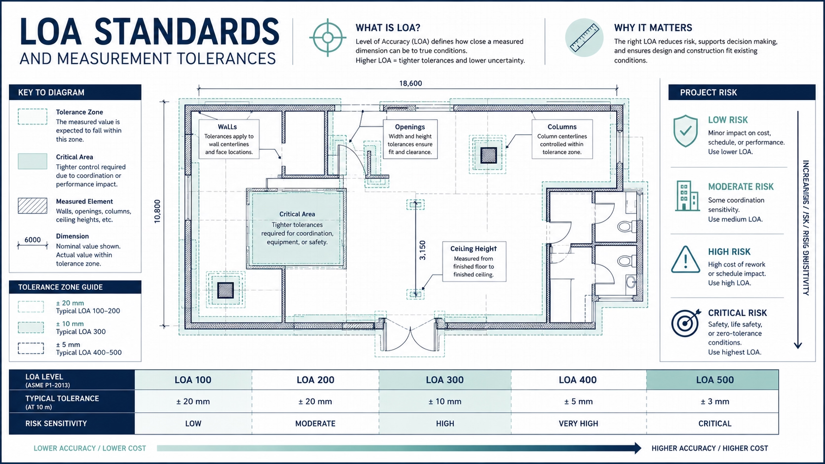
USIBD Level of Accuracy standards give project teams a framework for specifying accuracy in building documentation. In plain language, the standard helps answer three questions: how accurate does this documentation need to be, how will that accuracy be described, and how will stakeholders know whether the deliverable meets the requirement. This is useful because “accurate” can mean different things to different teams.
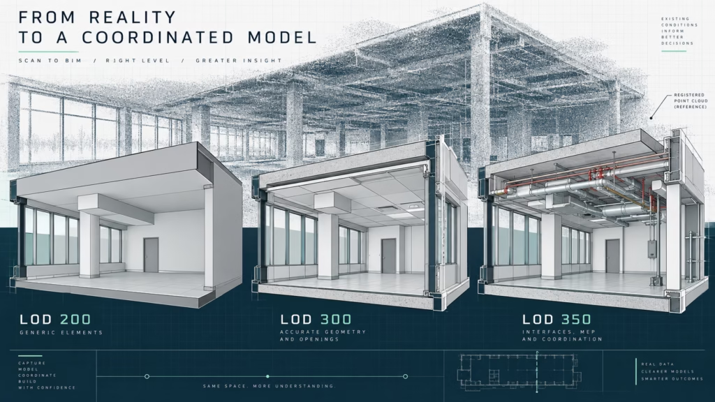
LOA is especially helpful in scan-to-BIM and scan-to-CAD projects. A laser scan may capture detailed spatial data, but the final deliverable still depends on how that data is processed, drafted, or modelled. A Revit model, for example, is an interpreted representation of the point cloud. If the model scope is not defined, one team may expect detailed irregular geometry while another delivers simplified design-ready elements. LOA helps clarify that expectation.
LOA should be applied selectively. Not every element in a building needs the highest accuracy. A general planning model may need a lower accuracy level than a detailed coordination model. A corridor wall may not need the same tolerance as a stair, shaft, façade detail, or custom millwork area. The best practice is to define accuracy requirements for the elements that carry project risk.
Measurement Tolerances in As-Built Surveys
Measurement tolerances in as-built surveys define the acceptable difference between the documented condition and the measured site condition. A tolerance might apply to wall locations, openings, column positions, ceiling heights, floor levels, equipment locations, or modelled elements. Tolerance should be defined based on what the drawing or model will be used for. The more risk attached to a dimension, the more carefully tolerance should be specified.
A simple planning floor plan may allow broader tolerance because it supports early layout decisions. A renovation-grade CAD file usually needs tighter tolerance because it may support design and contractor pricing. A scan-to-BIM model used for coordination may require more specific accuracy by element type. A prefabrication or detailed coordination workflow may require even tighter control. The practical rule is to match tolerance to the consequence of being wrong.
Tolerance should also be realistic. Existing buildings are not perfect. Walls may be out of plumb, floors may slope, ceilings may vary, and older structures may not follow ideal geometry. The documentation team must decide whether to represent these irregularities exactly, simplify them for design use, or note them where they matter. Architects and engineers should discuss this before drafting or modelling begins.
Laser Scanning Accuracy for Buildings vs Manual Measurement
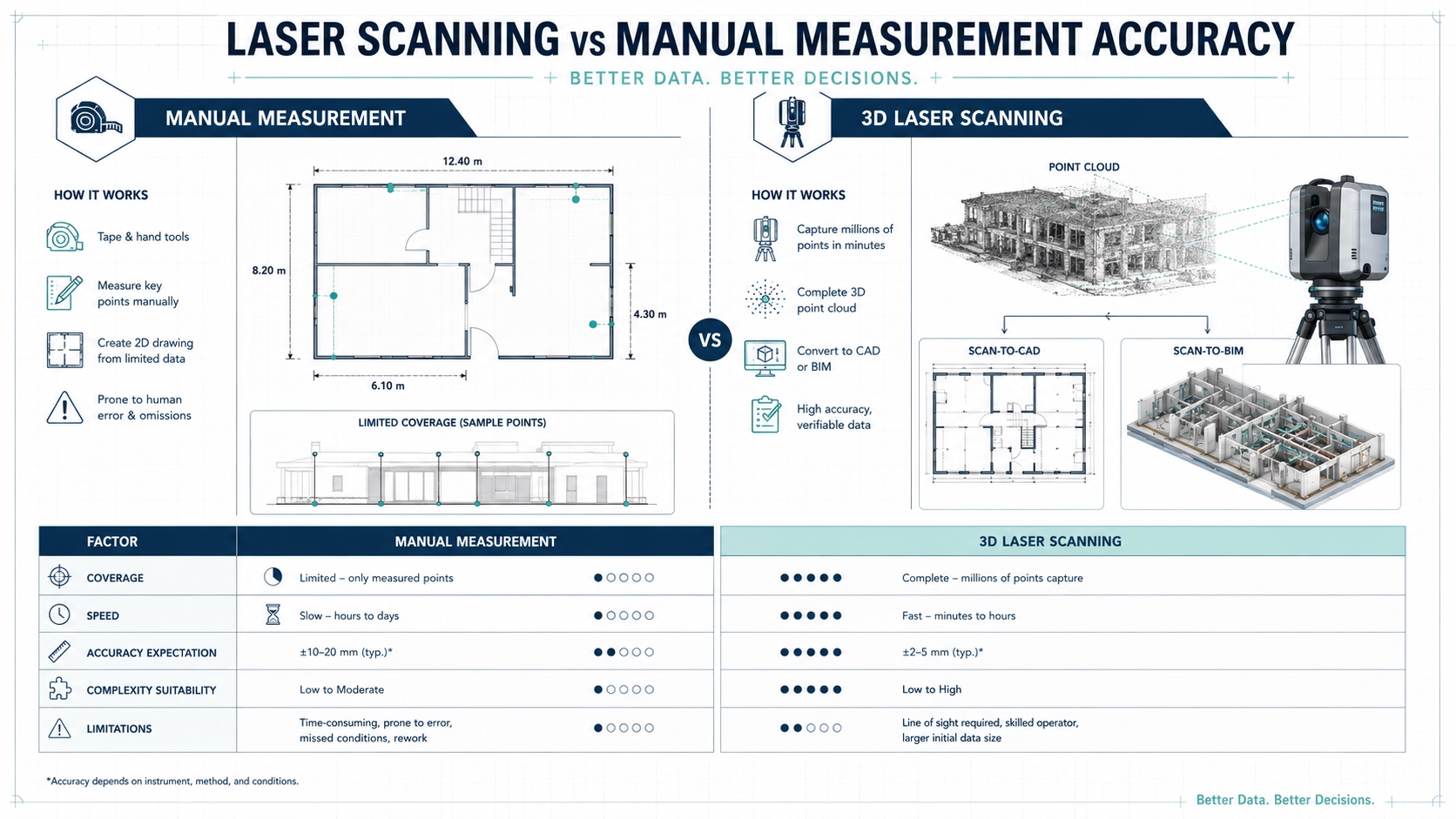
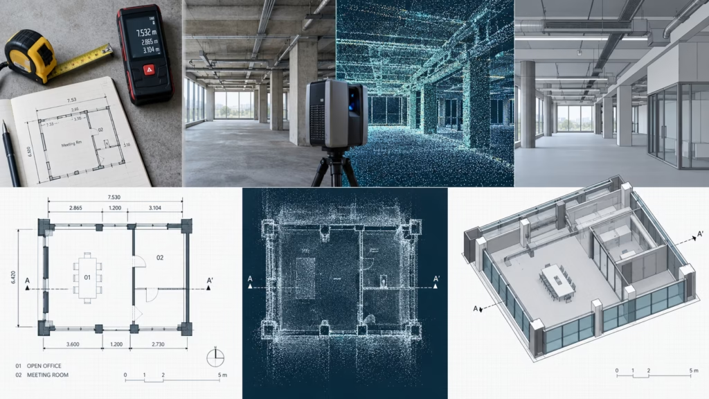
Laser scanning accuracy for buildings is usually stronger than manual measurement when the project involves complex geometry, many rooms, multiple levels, high ceilings, exposed structure, irregular conditions, or dense visible systems. A scanner captures a large amount of visible spatial data that can be registered into a point cloud. This point cloud can then support CAD drawings, Revit models, sections, elevations, and quality checks. The benefit is not only precision, but coverage.
Manual measurement can still be appropriate for simple, low-risk spaces. A small room, basic office, or early planning exercise may not require 3D laser scanning. Manual tools can produce useful drawings when the geometry is simple and the cost of small errors is low. The risk appears when manual measurements are used for complex renovation, contractor pricing, or coordination work where missed dimensions can create downstream cost.
The key difference is that manual measurement is selective, while laser scanning is more comprehensive for visible conditions. Manual measurement records chosen dimensions. Laser scanning records a broader measured environment. However, scanning still has limitations: it captures visible surfaces by line of sight and does not see through walls, ceilings, floors, or concealed assemblies. The practical takeaway is to choose the method based on project risk and required deliverables.
Typical Accuracy Expectations by Method and Use Case
Accuracy expectations should be defined by project use, not by a generic promise. The table below gives practical planning categories. These are not universal guarantees; they are examples of how project teams can think about tolerance, risk, and documentation method.
| Use case | Common documentation method | Accuracy expectation | Practical note |
|---|---|---|---|
| Real estate or early planning | Basic measurement or simple floor plan | General layout accuracy | Good for communication, not technical coordination |
| Simple renovation planning | Manual measurement or measured CAD floor plan | Moderate tolerance may be acceptable | Suitable when geometry is simple and risk is low |
| Renovation-grade as-built CAD | Manual measurement with QA or scan-to-CAD | Tighter tolerance should be defined | Useful for architects, designers, and contractors |
| Complex existing building | 3D laser scanning and CAD deliverables | Higher confidence in visible conditions | Useful when old drawings are unreliable |
| MEP coordination | 3D laser scanning and scan-to-BIM | Element-specific tolerance should be defined | Important for visible services and tight clearances |
| Structural coordination | Scanning, survey control, CAD/BIM review | Critical elements need clear tolerance | Engineer input may be required |
| Prefabrication support | High-control scanning and model verification | Tight tolerance and QA required | Must be scoped carefully before capture |
| Facility records | Point cloud, CAD, BIM, or hybrid package | Depends on future use | Documentation should include limitations |
The most important point is that “accurate” should not be treated as a single number for the entire building. A project may need high accuracy in one zone and moderate accuracy elsewhere. For example, a millwork wall, stair opening, mechanical room, or façade may need tighter tolerance than a general storage area. A good provider should help define these differences.
Why Scanner Accuracy Is Not the Same as Drawing Accuracy
Scanner accuracy and drawing accuracy are related, but they are not the same. A scanner may capture high-quality spatial data, but the final drawing or model still depends on registration, interpretation, drafting, modelling, and quality control. A point cloud can be highly detailed, while a floor plan created from it may still be simplified depending on scope. The deliverable accuracy is what matters to the project team.
Point cloud registration is one important step. Multiple scan positions must be aligned into a coordinated dataset. If registration is poor, the resulting drawings or models may inherit alignment issues. A provider should be able to explain how registration is checked and whether scan coverage is sufficient for the required deliverables. This is especially important for large or multi-level buildings.
Drafting and modelling decisions also affect accuracy. A drafter may trace walls from a point cloud into CAD. A BIM technician may model walls, columns, floors, and openings in Revit. Existing buildings often contain irregular geometry, so the team must decide how much to simplify and how much to represent exactly. The practical takeaway is to ask about deliverable verification, not only scanner specifications.
How Inaccurate As-Builts Create Change Orders and Rework
Inaccurate as-built drawings can create change orders when the proposed design does not fit the actual building. A wall may be in a different location than shown. A ceiling height may be lower than assumed. A stair opening may not align with the drawing. A column, beam, shaft, or visible service route may conflict with the proposed work. When these issues appear during construction, they can trigger redesign, delay, or additional cost.
Inaccurate as-builts can also affect contractor estimates. Contractors price work based on drawings, site visits, assumptions, and risk. If the drawings are unreliable, contractors may add contingencies or exclude uncertain work. If they rely on incorrect drawings, the project may face scope disputes later. Accurate floor plans for renovation help contractors understand the existing conditions more clearly before bidding.
Rework is especially expensive when materials are fabricated or ordered from incorrect dimensions. Custom millwork, glazing, steel, stairs, mechanical components, and prefabricated items can all be sensitive to measurement accuracy. If the as-built documentation is wrong, the project may need field modifications or replacement materials. The practical rule is to use stronger accuracy controls when fabrication or tight fit matters.
How Accuracy Supports Permit and Consultant Coordination
Accurate as-built drawings can support permit and consultant coordination by giving the design team a more reliable existing-condition base. Renovation projects often need to distinguish what exists from what is proposed. If the existing-condition drawings are inaccurate, the proposed drawing set may contain conflicts or inconsistencies. This can slow review, pricing, and coordination.
Accuracy does not guarantee permit approval. Permit approval depends on proposed design, zoning, building code requirements, municipality, consultant responsibility, and project-specific conditions. However, accurate existing-condition documentation can help architects, designers, engineers, and consultants prepare clearer drawings. The practical takeaway is that accuracy supports the process; it does not replace professional review.
Consultant coordination benefits when everyone works from the same measured base. Structural engineers, mechanical consultants, interior designers, contractors, and owners may all need to understand the same existing building. A shared CAD file, point cloud, or Revit model can reduce inconsistent assumptions. Accuracy matters because a shared base is only useful if it is reliable.
Accuracy Requirements for CAD vs BIM Deliverables
CAD deliverables and BIM deliverables should have different accuracy discussions. A CAD floor plan may focus on wall locations, openings, dimensions, elevations, and sections. A BIM model may focus on modelled element placement, levels, categories, object geometry, and coordination relationships. The project team should specify what needs to be accurate in the final format.
For CAD, accuracy questions often include: Are walls traced from field measurements or point cloud data? Are dimensions rounded or exact? Are wall thicknesses included? Are elevations and sections included? Are sloped or irregular conditions represented? Are inaccessible areas noted? These questions help define whether the CAD file is suitable for design or only for early planning.
For BIM, accuracy questions often include: What elements will be modelled? What level of accuracy applies to each element? Will irregular geometry be simplified or represented? Are visible MEP systems included? What Revit version is used? Will the model be checked against the point cloud? The practical recommendation is to define BIM accuracy by element and use case, not just by saying “Revit model.”
Scan-to-CAD vs Scan-to-BIM vs Standard Floor Plans
Scan-to-CAD, scan-to-BIM, and standard floor plans serve different accuracy needs. Standard floor plans may be enough for marketing or early planning. Scan-to-CAD is stronger when accurate 2D drawings are needed for renovation design, contractor pricing, or permit-support workflows. Scan-to-BIM is stronger when the project requires model-based coordination, Revit workflows, or complex existing-condition documentation.
| Documentation type | Best used for | Accuracy considerations |
|---|---|---|
| Standard floor plans | Real estate, early planning, simple layouts | Suitable for communication, not high-risk coordination |
| Measured CAD floor plans | Renovation planning and design base | Tolerance should be defined if used for design decisions |
| Scan-to-CAD | Accurate 2D as-built drawings | Point cloud can improve visible-condition reliability |
| Scan-to-BIM | 3D coordination and Revit workflows | Accuracy must be defined by model elements and scope |
| Point cloud only | Technical reference and future extraction | Useful if the project team can work directly with scan data |
| Full as-built package | Complex renovation, commercial, facility documentation | Should include scope, tolerances, file formats, and limitations |
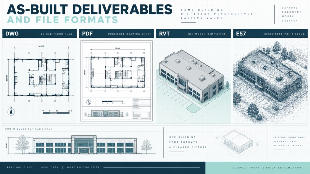
The correct deliverable depends on what the project team will do next. If the architect needs DWG files, a basic PDF is not enough. If the engineer needs a Revit model, CAD-only delivery may not support coordination. If the contractor only needs a dimensioned plan for a simple project, full BIM may be unnecessary. The practical takeaway is to match accuracy and deliverables to the actual workflow.
How to Verify As-Built Drawing Accuracy
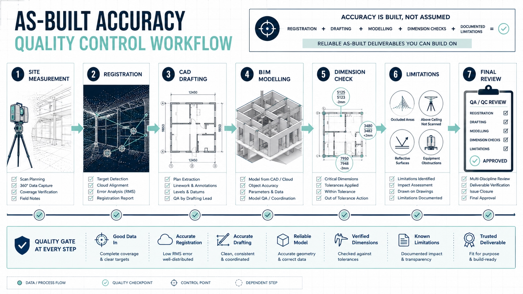
As-built drawing accuracy can be verified through a combination of quality control steps. These may include checking dimensions against field measurements, comparing CAD linework to the point cloud, reviewing model elements against scan data, checking registration reports, validating critical dimensions, and documenting assumptions or exclusions. The verification method should match the project risk.
For laser scanning projects, ask how the point cloud is registered and checked. Ask whether the provider reviews the final drawings or model against the point cloud. Ask whether critical areas are checked separately. Ask whether inaccessible zones are marked. This helps the project team understand how the provider controls accuracy beyond the initial scan.
For manual measurement projects, ask how measurements are checked and whether critical dimensions are verified. A second check may be needed for key walls, stairs, openings, or custom-fit areas. Manual measurement can work well for simple projects, but quality control becomes more important when drawings are used for construction decisions. The practical rule is to verify the dimensions that carry the highest risk.
Accuracy Questions to Ask Your As-Built Contractor
Architects, engineers, and contractors should ask accuracy questions before hiring an as-built provider. The goal is to understand how the provider defines, captures, drafts, verifies, and communicates accuracy. A provider who only says “our drawings are accurate” is not giving enough information for a technical project.
| Question | Why it matters |
|---|---|
| What tolerance will apply to the deliverables? | Prevents vague accuracy expectations |
| Do you follow LOA or another accuracy framework? | Helps align scope with project requirements |
| What measurement method will you use? | Manual measurement, laser scanning, or hybrid workflows differ |
| Will the deliverables be checked against a point cloud? | Important for scan-to-CAD and scan-to-BIM |
| What elements are included in the accuracy requirement? | Not every wall, ceiling, or system may be in scope |
| How are inaccessible areas documented? | Prevents false confidence in missing areas |
| How do you handle irregular geometry? | Existing buildings are rarely perfect |
| What file formats are delivered? | CAD, Revit, IFC, PDF, and point cloud workflows differ |
| What QA process is included? | Quality review affects deliverable reliability |
| What limitations will be stated in the final package? | Helps downstream teams use the documentation correctly |
These questions are especially important for B2B projects where design liability, contractor pricing, and coordination risk are involved. A clear accuracy conversation protects both the client and the provider. The practical takeaway is to require accuracy requirements in writing before field capture begins.
Questions Engineers Should Ask About Accuracy
Engineers should ask which elements are captured and how they are represented. Structural elements, ceiling heights, slabs, columns, beams, openings, shafts, stairs, and visible services may all affect engineering decisions. If a required element is not included in scope, the engineer should know before relying on the documentation.
Engineers should also ask whether the documentation distinguishes measured data from interpreted data. A point cloud records visible surfaces, but modelled elements may involve assumptions, simplification, or interpretation. If hidden structure or concealed services are relevant, the project may require additional investigation. The practical takeaway is that as-built accuracy applies only to what was captured and included.
Engineers should ask for critical dimensions to be verified when those dimensions affect design decisions. Not every dimension carries the same risk. Load paths, clearances, openings, slab edges, stair geometry, and equipment zones may require special attention. The provider should know which dimensions are critical before the site visit.
Questions Contractors Should Ask About Accuracy
Contractors should ask whether the drawings are suitable for estimating, coordination, or construction planning. A marketing floor plan or early planning drawing may not have enough detail for contractor pricing. A renovation-grade as-built drawing should identify dimensions and conditions relevant to scope. The contractor should understand what the drawings include before relying on them.
Contractors should ask whether the site was fully accessible during measurement. Locked rooms, blocked walls, inaccessible ceilings, or occupied areas can create missing information. If the drawings include limitation notes, contractors should review them before pricing. The practical recommendation is to treat limitation notes as part of the drawing package.
Contractors should ask whether the drawings were created from manual measurement, laser scanning, CAD conversion, or scan-to-BIM. Each method has different strengths and limits. For high-risk projects, a point cloud or scan-to-CAD base may provide stronger confidence than manually redrawn old plans. The practical takeaway is to understand the data source before pricing from the drawings.
Common Accuracy Mistakes in As-Built Documentation
A common accuracy mistake is using old design drawings as current as-built drawings. Original drawings may not show field changes, previous renovations, tenant improvements, or building movement over time. They can be useful references, but they should be verified before being used as a design base. The practical rule is to treat old drawings as background information, not measured proof.
Another mistake is assuming a Revit model is automatically accurate. A BIM model may look precise, but it is only as reliable as the data and modelling process used to create it. A model created from old drawings may be less reliable than a CAD plan created from current laser scanning. Accuracy depends on source data, scope, modelling decisions, and QA.
A third mistake is failing to define tolerance by project area. Some elements may need high accuracy, while others may not. If the entire building is treated the same way, the client may overpay for unnecessary detail or under-document critical areas. Accuracy should be concentrated where it affects design, pricing, coordination, or construction risk.
A fourth mistake is ignoring hidden conditions. Laser scanning captures visible surfaces. Manual measurement records accessible dimensions. Neither method confirms concealed structure, pipes, wiring, or assemblies behind walls unless those conditions are visible or separately investigated. A good as-built package should state these limitations clearly.
Practical Decision Matrix: What Accuracy Level Do You Need?
A practical decision matrix helps teams match accuracy to project use. The goal is not always maximum accuracy. The goal is appropriate accuracy for the decision being made. Over-specifying accuracy can waste budget. Under-specifying accuracy can create rework.
| Project situation | Recommended accuracy approach | Why it fits |
|---|---|---|
| Property marketing | Basic floor plan accuracy | Layout clarity matters more than technical tolerance |
| Early feasibility | Measured plan with reasonable tolerance | Enough for planning without over-documenting |
| Interior renovation | Accurate floor plans and CAD base | Supports designers and contractor pricing |
| Custom millwork | Verified dimensions and selected elevations | Fit and fabrication risk are higher |
| Addition or exterior change | Floor plans, elevations, sections, measured exterior | Existing/proposed coordination matters |
| Commercial tenant improvement | As-built CAD or scan-to-CAD | Supports landlord, tenant, designer, and contractor |
| Structural coordination | Critical elements verified and documented | Engineering decisions depend on real geometry |
| MEP retrofit | 3D scanning and possible scan-to-BIM | Spatial coordination and clearances matter |
| Facility record | Point cloud, CAD, or BIM with notes | Long-term use requires clear limitations |
| Prefabrication | High-control scan and deliverable QA | Small errors can become expensive |
The decision matrix should be discussed before the site visit. Once the provider knows which areas carry the highest risk, the measurement plan can be adjusted. The practical takeaway is that accuracy should be designed into the scope, not inspected after the fact.
The MeasureBuilt Existing Conditions Framework for Accuracy
The MeasureBuilt Existing Conditions Framework can be used to align accuracy requirements with project risk. The framework begins by identifying the project use: design base, contractor pricing, permit coordination, scan-to-CAD, scan-to-BIM, facility documentation, or critical coordination. This step matters because each use case requires a different level of accuracy and detail.
The second step is selecting the measurement method. Simple spaces may be documented with manual measurement and quality checks. Complex spaces may require 3D laser scanning. Projects involving Revit, point clouds, high ceilings, irregular geometry, or visible MEP systems may require scan-to-CAD or scan-to-BIM. The measurement method should match the accuracy requirement.
The third step is defining deliverables and limitations. The package should state file formats, included areas, modelled elements, tolerance expectations, inaccessible areas, hidden-condition exclusions, and QA process. This makes the documentation easier to use downstream. The practical takeaway is that accuracy is not only a technical outcome; it is a communication process.
How to Prepare for an Accuracy-Driven Survey
Preparing for an accuracy-driven survey starts with defining the required deliverables. Tell the provider whether you need PDF plans, DWG files, elevations, sections, point clouds, Revit models, IFC exports, or BIM documentation. If critical areas require tighter tolerance, identify them before the site visit. The provider cannot prioritize what they do not know.
Prepare the site by ensuring access to all required areas. Locked rooms, cluttered spaces, blocked walls, active construction zones, and inaccessible ceilings can reduce documentation quality. If 3D laser scanning is used, clear line of sight matters. The building does not need to be empty, but critical geometry should be visible and accessible.
Prepare by sharing available records. Old drawings, CAD files, previous permit drawings, tenant plans, photos, and renovation notes can help the measurement team understand the property. These records should not replace current measurement when accuracy matters, but they can help the team plan capture and compare known conditions. The practical takeaway is that preparation improves both accuracy and turnaround.
Key Takeaways
As-built drawing accuracy is not just a technical detail. It affects design confidence, contractor pricing, consultant coordination, change order risk, and construction planning. Architects, engineers, and contractors should define accuracy requirements before fieldwork begins.
USIBD LOA standards help project teams communicate accuracy expectations more clearly. LOA is useful because it moves the conversation from vague promises to specified requirements. The best accuracy approach defines tolerance, deliverables, included elements, verification method, and limitations.
3D laser scanning can provide a stronger measured base than manual measurement for complex buildings, but scanner accuracy is not the same as deliverable accuracy. The final CAD drawing or BIM model still depends on registration, drafting, modelling, QA, and scope. Talk to us about accuracy requirements for your project before choosing a measurement method.
FAQ
What is as-built drawing accuracy?
As-built drawing accuracy is the degree to which drawings, CAD files, floor plans, or BIM models match the actual building conditions measured on site. It affects wall locations, openings, levels, stairs, columns, ceiling heights, and other documented features within scope. Accuracy should be defined by tolerance, measurement method, deliverable type, and quality control process.
What are level of accuracy standards?
Level of accuracy standards help project teams define how closely building documentation should match real-world conditions. They are used to reduce ambiguity between clients, architects, engineers, contractors, and documentation providers. Instead of asking for “accurate drawings,” the team can specify the required accuracy level for different elements or deliverables.
What is the USIBD LOA specification?
The USIBD LOA specification is a building documentation accuracy framework used to define and communicate accuracy expectations. It helps teams align on how accurate a drawing, model, or documented element should be. In practice, it is most useful when tied to specific deliverables, tolerances, verification methods, and project risk areas.
Are laser-scanned as-built drawings always accurate?
Laser scanning can create a strong measured base, but the final drawing or model is only as reliable as the full workflow. Scan planning, point cloud registration, drafting, modelling, QA, scope, and site access all affect deliverable accuracy. A scanner may capture detailed data, but the CAD or BIM output still needs verification.
What are typical measurement tolerances in as-built surveys?
Typical measurement tolerances depend on project use. A marketing floor plan may allow broader tolerance, while renovation-grade CAD drawings, MEP coordination, structural work, or prefabrication may require tighter requirements. The correct tolerance should be defined before the survey based on what the drawings or model will be used for.
Is manual measurement accurate enough for as-built drawings?
Manual measurement can be accurate enough for simple, small, low-risk spaces when the deliverable is basic. It becomes less reliable for complex buildings, irregular geometry, many rooms, multiple floors, high ceilings, visible systems, or contractor coordination. For higher-risk projects, 3D laser scanning or scan-to-CAD may provide a stronger measured base.
How do inaccurate as-built drawings cause change orders?
Inaccurate as-built drawings can cause change orders when proposed work does not fit the actual building. Wrong dimensions, missed openings, incorrect ceiling heights, or unrecorded visible constraints can lead to redesign, material changes, fabrication problems, or installation delays. Better existing-condition documentation helps identify more issues before construction begins.
What should architects ask about as-built accuracy?
Architects should ask what tolerance applies, what measurement method is used, whether the drawings are checked against a point cloud, what deliverables are included, how irregular geometry is handled, and what limitations are stated. They should also confirm whether the files are suitable for design, permit support, CAD drafting, or Revit workflows.
What should contractors ask before pricing from as-built drawings?
Contractors should ask whether the drawings are renovation-grade, whether all required areas were accessible, what measurement method was used, what limitations apply, and whether critical dimensions were verified. They should also check whether the drawings are suitable for estimating or only for early planning. This reduces pricing assumptions and scope disputes.
How do I choose the right accuracy level for my project?
Choose the accuracy level based on risk. A simple planning project may need basic measured drawings. A renovation, tenant improvement, structural coordination, MEP retrofit, or prefabrication project may need tighter tolerances and stronger QA. Talk to us about accuracy requirements for your project so the measurement method and deliverables match the actual use case.
Conclusion
As-built drawing accuracy matters because existing-condition documentation becomes the base for design, engineering, contractor pricing, renovation planning, and coordination. A drawing can look clean but still fail the project if tolerances, source data, scope, and verification are unclear. LOA standards, including USIBD-based accuracy thinking, help project teams define what “accurate” should mean before fieldwork begins. Manual measurement may be appropriate for simple spaces, while 3D laser scanning can provide a stronger base for complex buildings, CAD drafting, Revit modelling, and scan-to-BIM workflows. The best approach is to define accuracy requirements early, identify critical areas, confirm deliverables, and ask how the provider verifies the final drawings or model. Talk to us about accuracy requirements for your project before choosing your as-built documentation scope.

Analyse this page with AI
Want a summary, fact-check, or an RFP template built around these measurement standards? Send this page directly to your favourite AI model.
Content and prompt will be copied to clipboard for some models.